Prior to the start of the Hawken Project period in May, I had already done some work towards this project in order to hit the ground running as soon as the regular rotation ended. Before I began to start designing my own robot, I wanted to make sure that I would have all of the parts I needed and a baseline understanding of how to get one working. To accomplish this, I bought and assembled a simple kit robot to get something moving and get all of the electronics I would use in my own robot.
 |
| Photos of the Viper Kit |
During the first week of spring break, I started to do some more research on antweight combat robots in order to learn about their constraints, match conditions, and find design inspiration. I was able to find lots of different examples of robots with many different types of materials, weapons, and drive styles. Over the second week of spring break, I started to design my own robot. I decided to start designing a robot for the plastic-only antweight class as I would be able to print all of the parts that I needed on my 3D printer at home. For this robot, I chose to do a vertical spinner as I knew that would be easy for me to accomplish and I had seen enough examples of plastic robots with that style of weapon that I knew that the concept would work.
To design the robot, I used the computer-aided design (CAD) software Autodesk Inventor. The nice thing about Autodesk products is that despite normally costing thousands of dollars a year to use, they are all completely free for students and educators. I have had lots of prior experience with Inventor before because my dad has an educational license and we learned how to 3D model together when we first got a 3D printer when I was in 5th grade. I also used Inventor throughout my time doing the VEX Robotics Competition in High School to design our robots prior to building them.
Inventor allowed me to use 3D files of the electronics, like the motors and receiver, that I had downloaded off the internet in assemblies where I could reference them while designing the robot around them. There were some problems, though, with the way that I was designing parts. Instead of thinking through each dimension and reference carefully, I would place shapes and references in any way that would get me the shape I wanted in the end. This caused massive headaches whenever I realized I would need to change something, as one simple change caused a butterfly effect of errors in the files of countless other parts.
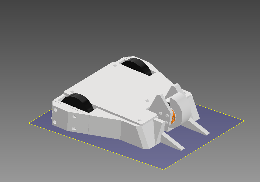 |
| Screenshots of my CAD model |
Once I had everything designed to a point I thought was final, then came the time to start printing my parts. The type of filament that I decided to use was Inland's PLA+ because of the types of filaments allowed in the plastic class, Pla, Pla+, Pet, Petg, and ABS, PLA+ is the most suitable for combat robotics given its durability. One of the biggest issues that I ran into while printing my parts was figuring out my tolerances. If I don't add enough gaps to the parts I print, stuff is not going to fit together and I went through tons of prints trying to figure out my tolerances. For most parts, 0.1-0.2 mm on all sides did the trick. For one particular hole for a ball bearing on my main chassis, though, finding that tolerance involved about 4 nearly 10-hour-long prints to get right.
 |
| All of the 3D Prints for this robot |
Another major challenge that I ran into was trying to keep the robot under the weight limit. 1 lb is not a lot and it became quickly apparent that my chassis was much larger than it needed to be. In order to cut weight from the robot, I started to remove material from the design in order to save weight and print parts using settings that used less material at the cost of strength. At the end of all of my attempted weight cuts, this robot still ended up about 10 grams heavier than it should be. At this point though, further weight cuts would compromise the integrity of the structure and given my problems with the CAD it would have been easier to redesign the robot from scratch instead of making this design smaller.
 |
| The final product |
 |
| 1 pound is 453.5924 grams |
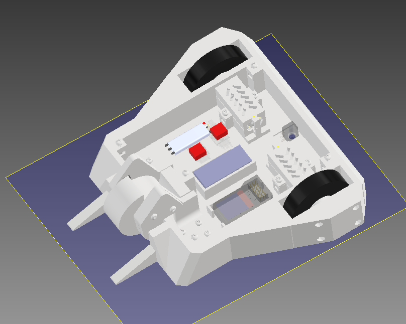
 |
| The insides of the robot |
The last thing that I did for my project prior to the start of the Intensives period was build a testing box for my robot in the woodshop and fab lab. The weapons on these robots can get quite fast, given that the motors are spinning at thousands of RPM; when doing a spin-up test, the robot is in an enclosed space for everyone's safety. The box that I built is 2'x2'x15" made of plywood and has a 1/4" sheet of clear polycarbonate on top. The top cover is attached with door hinges and latches that I bought from Home Depot which gave me the best way to be able to open the box easily but also keep it securely closed during testing. Drilling holes in the polycarbonate was a pain though as the bigger holes took nearly 15 minutes to drill by hand and the polycarbonate would melt a bit near the end causing some trouble.
 |
The testing box
|
 |
| The damage it did to another chassis print |


Comments
Post a Comment